
Product Introduction
I. Product Overview:
The stabilized pressure pump control box is a device used to control the start, stop and adjustment of the stabilized pressure pump. The stabilized pressure pump is a type of fire pump, which is used in automatic sprinkler systems and hydrant water supply systems to keep the system water pressure in the required pressure state. Once a sprinkler or hydrant discharges water, it can provide the water volume and pressure required for fire-fighting water.
The stabilized pressure pump control box is a device used to control the start, stop and adjustment of the stabilized pressure pump. The stabilized pressure pump is a type of fire pump, which is used in automatic sprinkler systems and hydrant water supply systems to keep the system water pressure in the required pressure state. Once a sprinkler or hydrant discharges water, it can provide the water volume and pressure required for fire-fighting water.
II. Structural Composition
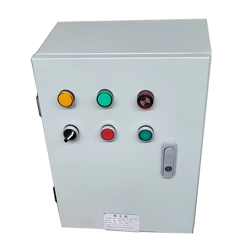
1. Cabinet: As the outer shell of the control box, it protects the internal electrical components. It is generally made of metal materials with certain strength and protection level.
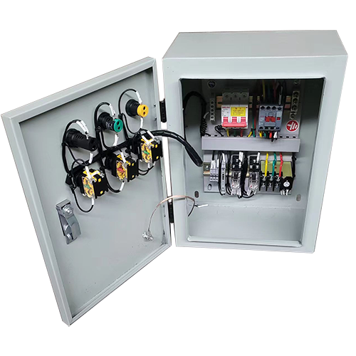
2. Control Mechanism: Contains various electrical components such as circuit breakers, contactors, relays, etc. The circuit breaker is used to cut off the circuit to protect the equipment from overload and short circuit; the contactor is used to control the on-off of the circuit to realize the start and stop control of the stabilized pressure pump; the relay can realize signal conversion and expansion, and perform logical control.
3. Display and Operation Components: Including control panel, buttons, indicator lights, etc. The control panel (optional) can display the working status parameters of the stabilized pressure pump, such as pressure, current, voltage, etc.; the buttons are used for manual control of the start, stop and working mode switching of the stabilized pressure pump; the indicator lights intuitively show the operating status of the control box and the stabilized pressure pump, such as whether the power is on, whether the pump is running, whether there is a fault, etc.
1. Cabinet: As the outer shell of the control box, it protects the internal electrical components. It is generally made of metal materials with certain strength and protection level.
2. Control Mechanism: Contains various electrical components such as circuit breakers, contactors, relays, etc. The circuit breaker is used to cut off the circuit to protect the equipment from overload and short circuit; the contactor is used to control the on-off of the circuit to realize the start and stop control of the stabilized pressure pump; the relay can realize signal conversion and expansion, and perform logical control.
3. Display and Operation Components: Including control panel, buttons, indicator lights, etc. The control panel (optional) can display the working status parameters of the stabilized pressure pump, such as pressure, current, voltage, etc.; the buttons are used for manual control of the start, stop and working mode switching of the stabilized pressure pump; the indicator lights intuitively show the operating status of the control box and the stabilized pressure pump, such as whether the power is on, whether the pump is running, whether there is a fault, etc.
III. Working Principle
- Pressure Monitoring and Control: The control box connects to a pressure sensor to monitor the water pressure of the fire water pipe network in real time. When the pipe network pressure is lower than the set lower limit, the pressure sensor transmits a signal to the controller (such as PLC or relay logic circuit) in the control box. The controller triggers the contactor to close, connects the power supply of the stabilized pressure pump, and starts the pump to pressurize the pipe network. When the pipe network pressure rises to the set upper limit, the pressure sensor feeds back the signal again, and the controller controls the contactor to open, so that the stabilized pressure pump stops running. This maintains the pipe network pressure within a certain range.
- Automatic and Manual Switching: It has two control modes: automatic and manual. In automatic mode, the control box automatically controls the start and stop of the stabilized pressure pump according to the signal of the pressure sensor; the manual mode is convenient for staff to directly control the start and stop of the stabilized pressure pump through the buttons on the control box during debugging, maintenance or when the automatic control fails.
- Fault Monitoring and Protection: Internal electrical components also monitor the operating status of the stabilized pressure pump, such as monitoring current through current transformers. When faults such as overload, short circuit, phase loss, and motor overheating occur, the corresponding protection devices (such as circuit breaker tripping, thermal relay action) will quickly cut off the circuit to prevent the fault from expanding. At the same time, the fault indicator light on the control box will be on to remind the staff to carry out maintenance.
IV. Installation and Maintenance Points
- Installation Environment: Try to choose a dry, well-ventilated place without corrosive gas and dust for installation. If it can only be installed in a humid environment, strengthen dehumidification measures. At the same time, ensure that there is enough space around the control box for operation and maintenance.
- Wiring Inspection: During installation, ensure that the wiring of power lines, signal lines, etc. is correct and firm to avoid virtual connection or wrong connection that causes the control box to fail to work normally or malfunction. Regularly check whether the wiring is loose or aging, and deal with problems in time.
- Component Inspection: Regularly check the electrical components in the control box, such as whether the contacts of circuit breakers, contactors, relays are worn or ablated, and whether the coils are overheated; check whether the heat dissipation device is operating normally; check whether the desiccant of the dehumidification device is invalid and replace it in time.
- Function Test: Regularly test the functions of the control box, including automatic start-stop function, manual control function, fault alarm and protection function, to ensure that it can work reliably when needed.
- Selection Tips: When selecting or ordering, please provide key parameters such as water pump motor power, rated current, control voltage, pressure setting range and sensor type to ensure the best matching of the product.
V. Sample diagrams are for reference only.