
Product Introduction
Technical Specification for General Fan Control Box
(Applicable power: ≤11kW three-phase asynchronous motor)
(Applicable power: ≤11kW three-phase asynchronous motor)
I. Product Overview
This distribution box is specially designed for three-phase fans with power ≤11kW. It adopts an electromechanical integration control scheme, integrating motor starting, overload protection and operation monitoring functions. It complies with the GB/T 14048.4 electrical standard and is suitable for heating, ventilation, industrial exhaust and other occasions.
This distribution box is specially designed for three-phase fans with power ≤11kW. It adopts an electromechanical integration control scheme, integrating motor starting, overload protection and operation monitoring functions. It complies with the GB/T 14048.4 electrical standard and is suitable for heating, ventilation, industrial exhaust and other occasions.
II. Core Configuration Scheme
| Components | Specification Parameters | Function Description |
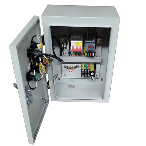
| Main circuit | ||
| Isolating electrical appliance | 63A 3P isolating switch (ACB/MCCB) | Maintenance isolation and short-circuit protection |
| Contactor | LC1-D32 (25A/380V) or equivalent grade | Motor start-stop control (AC-3 category) |
| Control circuit | ||
| Control voltage | 220V AC/24V DC (optional) | Safety isolation transformer optional |
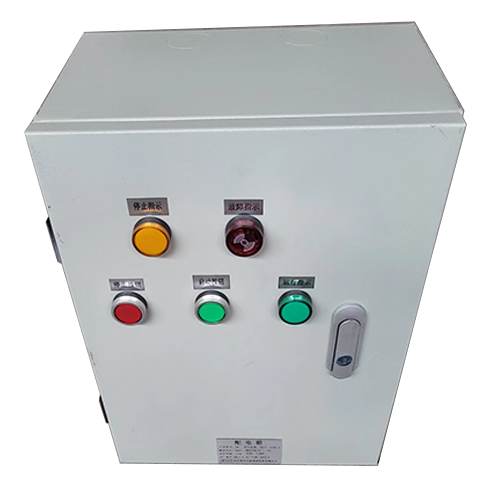
| Button | Green start/red stop/mushroom head emergency stop | IP30, 55, 65 protection grades optional |
| Indicator light | 220V LED (red - running/green - power) | With nameplate |
| Box body | 400×500×200mm (W×H×D) | Cold-rolled steel plate 1.2mm, RAL7035 color code |
| Installation method | Wall-mounted (pre-embedded mounting plate) | Indoor/outdoor (with canopy) |
III. Functional Features
1. Start-stop Control
- Direct start by contactor, supporting remote/local dual control modes
- Mechanical self-locking structure to prevent misoperation
2. Protection Mechanism
- Bimetallic strip thermal relay provides **asymmetric overload protection**
- Setting current is precisely adjustable (±15% accuracy)
- Manual reset after fault tripping to ensure safety
3. Status Monitoring
- Door-mounted indicator light group:
- Green power indicator light (with fuse monitoring)
- Red fan running indicator
- Emergency stop button directly cuts off the control circuit (compliant with EN 60204 safety standard)
Feature Description:
- Front door design with an opening angle of ≥120°
- Buttons/indicators tilted at 15° for easy observation
- 20% internal space reserved for expansion
- Front door design with an opening angle of ≥120°
- Buttons/indicators tilted at 15° for easy observation
- 20% internal space reserved for expansion
V. Technical Parameters
VI. Selection Guide
| Item | Parameters |
| Rated insulation voltage | 690V |
| Short-time withstand current | 6kA/1s |
| Degree of protection | IP30, IP54 (indoor) / IP65 (customized) |
| Conductor entry | G1" knockout (bottom/top) |
| Ambient temperature | -5℃~+40℃ |
| Fan power | Recommended contactors | Thermal relay setting range | Recommended cabinet dimensions |
| 4kW | LC1-D1210 | 7-10A | 400x300x200 |
| 7.5kW | LC1-D25 | 15-18A | 500x400x200 |
| 11kW | LC1-D32 | 22-25A | 500x400x200 |
Note: For altitudes exceeding 2000m, derating is required. In flammable environments, explosion-proof buttons must be equipped.
VII. Safety Certifications
- Complies with GB 7251.1 low-voltage switchgear standards
- Contactors/thermal overload relays are CCC/CE certified
- Grounding continuity resistance < 0.1Ω
- Complies with GB 7251.1 low-voltage switchgear standards
- Contactors/thermal overload relays are CCC/CE certified
- Grounding continuity resistance < 0.1Ω
This solution has been successfully applied in multiple industrial plant ventilation projects. Should you require electrical schematics, bill of materials (BOM), or protection class calculation reports, we can provide professional documents immediately.
VIII. The sample diagram is for reference only. Specific configurations can be customized according to user requirements. For customization, please provide information such as motor power, control method, and applicable location.