
Product Introduction
Product Introduction of Intelligent Control Box for Fire-Fighting Fans
(Adaptive motor power: ≤11kW | Exclusive for fire emergency)
(Adaptive motor power: ≤11kW | Exclusive for fire emergency)
I. Core Fire-Fighting Functions
1.Multiple Control Modes
| Mode | Control Logic | Priority |
| Manual mode | Direct start/stop via door-mounted buttons (emergency operation) | Highest |
| Automatic mode | Receiving signals from the fire alarm main unit (multi-line/bus) for linked start/stop | Secondary highest |
| Remote mode | Direct control via hard wires from the fire control room (multi-line system) | Programmable |
2. Fire Linkage Logic
mermaid
graph LR
A[Fire Alarm Main Unit Alarms] --> B{Automatic Mode Activated}
B --> C1[Multi-line Control: Hard Wire Connects to Start Terminal]
B --> C2[Bus Control: Receive MODBUS/CAN Messages]
C1 & C2 --> D[Fan Starts]
D --> E[Air Valve Actuator Links and Opens]
E --> F[Operation Signal Feeds Back to Fire Alarm Main Unit]
F --> G[Air Valve Closing Signal?]
G -- Yes --> H[Fan Automatically Stops]
II. Key Configuration List
III. Technical Parameters
| Functional Area | Configuration Description |
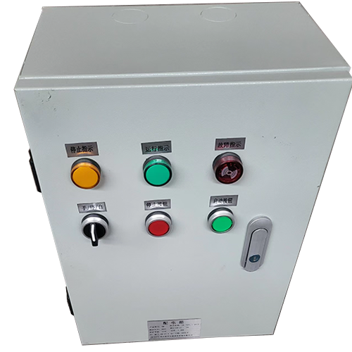
| Operation Panel | ▶ Manual/Auto Changeover Switch (with key lock) ▶ Start/Stop Buttons (red mushroom-head emergency stop) ▶ Three-color indicator lights: - Green light: Running - Yellow light: Standby - Red light (flashing): Fire fault |
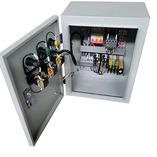
| Protection System | Thermal overload relay (fire-fighting dedicated type, such as JR36-F) ▶ Optional intelligent protector (Schneider GV4-P / Siemens 3UF7) - Short-circuit instantaneous protection - Phase loss locking - Locked-rotor inverse time protection |
| Fire-Fighting Interface | ▶ Multi-line system: 4-core hard wire terminals (start/stop/common/feedback) ▶ Bus system: RS485 communication terminal (supports Modbus-RTU) ▶ **Forced feedback terminals**: - Operating status (passive dry contact) - Fault alarm (normally closed contact) |
| Air Valve Linkage | Dedicated relay output: air valve opening signal (DC24V/2A) ▶ **Shutdown interlock**: Cut off the fan power immediately upon receiving the air valve closing signal |
| Parameters | Indicators |
| Control voltage | AC220V/380V dual-power self-adaptive |
| Fire signal input | Passive contact / DC24V (opto-isolated) |
| Feedback contact capacity | AC250V/5A (resistive load) |
| Response time | ≤3s (from receiving fire signal to starting) |
IV. Key Points for Engineering Installation
1. Wiring Specifications:
- Fire control lines shall use "fire-resistant copper core cables" (e.g., NH-KVV-4×1.5mm²)
- Power cables and signal cables shall be run in separate conduits (with a spacing of >200mm)
1. Wiring Specifications:
- Fire control lines shall use "fire-resistant copper core cables" (e.g., NH-KVV-4×1.5mm²)
- Power cables and signal cables shall be run in separate conduits (with a spacing of >200mm)
2. Grounding Requirements:
- Independent grounding terminal block (cross-sectional area ≥4mm²)
- Grounding resistance <1Ω
- Independent grounding terminal block (cross-sectional area ≥4mm²)
- Grounding resistance <1Ω
V. Recommendations from Fire Engineers:
1. Test the "manual-automatic switching function" quarterly (to prevent contact oxidation and failure)
3. Air valve linkage cables shall be protected with "metal hoses" (to prevent mechanical damage)
1. Test the "manual-automatic switching function" quarterly (to prevent contact oxidation and failure)
3. Air valve linkage cables shall be protected with "metal hoses" (to prevent mechanical damage)
VI. Ordering
▶ Required information: rated current of the fan, type of air valve actuator, brand and model of the fire alarm main unit, and other special requirements
▶ Required information: rated current of the fan, type of air valve actuator, brand and model of the fire alarm main unit, and other special requirements
VI. The sample diagram is for reference only