
Product Introduction
Instruction Manual for Motor Star-Delta (Y-Δ) Reduced-Voltage Starting Control
Applicable Object: Three-phase asynchronous motor (power ≥ 11kW, voltage 380V/50Hz)
Applicable Object: Three-phase asynchronous motor (power ≥ 11kW, voltage 380V/50Hz)
I. Starting Principle and Purpose
1. Necessity of Reduced-Voltage Starting
When the motor power is relatively large (usually ≥ 11kW), direct starting will generate an impact current of 6~8 times the rated current, leading to:
- A sudden drop in grid voltage (affecting other equipment)
- Mechanical impact (damaging couplings/belts)
- Misoperation of protection devices
2. Principle of Star-Delta Conversion
| Starting phase | Winding connection | Phase voltage | Starting current | Starting torque |
| Star (Y) | Ends of windings short-circuited | 220V | 1/3 of direct starting current | 1/3 of direct starting torque |
| Delta (Δ) | Head and tail connected in sequence | 380V | Full-voltage rated current | 100% rated torque |
Transition time: Usually set to 4~15 seconds (adjust according to load inertia), ensuring that the speed reaches 75%~85% of the rated speed before switching to Δ operation.
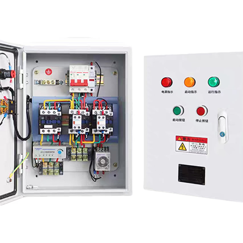
II. System Composition and Component Selection
1. List of Core Components
1. List of Core Components
| Components | Example models | Specification Requirements | Quantity |
| Main circuit breaker | Main circuit breaker | NM1-225S/3300 | 1 |
| AC contactor | CJX2-6511 (Δ operation) | AC-3 category, current ≥ I<sub>N</sub> | 3 |
| Thermal relay | R36-160J | Setting current ≈ I<sub>N</sub> (to prevent false tripping during Y-start) | 1 |
| Time relay | ST3PF (digital type) | Range 0.1~999s, accuracy ±1% | 1 |
| Button | LA38-11 | Green (start) / Red (stop) | 2 |
2. Protection Function Configuration
- Short-circuit protection: Main circuit breaker (instantaneous tripping)
- Overload protection: Thermal relay (only connected to the Δ circuit to avoid misoperation in the Y phase)
- Voltage loss protection: Contactor self-locking circuit
- Mechanical interlock: Normally closed contacts of KM<sub>Y</sub> and KM<sub>Δ</sub> are connected in series (to prevent simultaneous attraction)
III. Electrical Wiring Diagram and Action Logic
1. Main Circuit Wiring (see attached drawing)
mermaid
graph LR
L1/L2/L3 --> QF[Main Circuit Breaker] --> KM1[Main Contactor]
KM1 --> |U1/V1/W1| KM<sub>Y</sub>[Star Contactor] --> Short-circuit W2/U2/V2
KM1 --> |U1/V1/W1| KM<sub>Δ</sub>[Delta Contactor]
1. Main Circuit Wiring (see attached drawing)
mermaid
graph LR
L1/L2/L3 --> QF[Main Circuit Breaker] --> KM1[Main Contactor]
KM1 --> |U1/V1/W1| KM<sub>Y</sub>[Star Contactor] --> Short-circuit W2/U2/V2
KM1 --> |U1/V1/W1| KM<sub>Δ</sub>[Delta Contactor]
2. Control Circuit Action Process
mermaid
sequenceDiagram
participant SB1 as Stop Button
participant SB2 as Start Button
participant KT as Time Relay
participant KMY as Star Contactor
participant KMΔ as Delta Contactor
participant KM1 as Main Contactor
SB2->>+KT: Press start → KT is energized and starts timing
KT-->>KMY: Instantly pull in (star starting)
KMY-->>KM1: Auxiliary contact pulls in (main circuit is energized)
KT->>-KMΔ: Timing ends → Disconnect KMY
KT-->>+KMΔ: Simultaneously pull in KMΔ (switch to delta)
KMΔ-->>KM1: Maintain self-locking
> Key Wiring Notes:
- The 6 motor terminals (U1/U2, V1/V2, W1/W2) must be correctly marked;
- The output wires of KM<sub>Δ</sub> must be crossed strictly according to the phase sequence (U1-W2, V1-U2, W1-V2).
- The 6 motor terminals (U1/U2, V1/V2, W1/W2) must be correctly marked;
- The output wires of KM<sub>Δ</sub> must be crossed strictly according to the phase sequence (U1-W2, V1-U2, W1-V2).
IV. Commissioning Steps and Parameter Settings
1. No-load Commissioning Process
1. No-load Commissioning Process
| Steps | Operation | Expected phenomena |
| 1 | Disconnect the main circuit and only test the control circuit | KM<sub>Y</sub> pulls in, KT starts timing |
| 2 | Simulate the KT time expiration | KM<sub>Y</sub> releases, KM<sub>Δ</sub> pulls in |
| 3 | Connect to the main circuit (motor unloaded) | Y starting current ≤ 1.5I<sub>N</sub>, no impact during switching |
2. Setting Principles for Time Relay
- Light load (fans/water pumps): 4~8 seconds
- Heavy load (crushers/compressors): 10~15 seconds
- Formula reference: `t = (√J × N<sub>rated</sub>)/(9.55 × T<sub>Y start</sub>)`
(J - Moment of inertia in kg·m²; T<sub>Y start</sub> - Star starting torque in N·m)
- Light load (fans/water pumps): 4~8 seconds
- Heavy load (crushers/compressors): 10~15 seconds
- Formula reference: `t = (√J × N<sub>rated</sub>)/(9.55 × T<sub>Y start</sub>)`
(J - Moment of inertia in kg·m²; T<sub>Y start</sub> - Star starting torque in N·m)
V. Common Faults and Troubleshooting
| Fault phenomena | Possible causes | Troubleshooting methods |
| Tripping during startup | KM<sub>Y</sub>/KM<sub>Δ</sub> pull in simultaneously | Check mechanical interlocks and wiring |
| Severe vibration during switching | Conversion time is too short | Extend KT setting time (in +2-second steps) |
| Malfunction of thermal relay | Overload protection in Y phase takes effect | Move the thermal relay to the output terminal of KM<sub>Δ</sub> |
| Wrong motor rotation direction | Phase sequence of main circuit is reversed | Swap any two incoming phase lines |
VI. Safety Warnings
1. Live working is strictly prohibited: The main circuit breaker must be disconnected and voltage must be verified before switching contactors;
2. Modification of interlocks is forbidden: Removing the KM<sub>Y</sub>-KM<sub>Δ</sub> interlock may cause short circuits and explosions;
3. Mandatory grounding requirements: The motor housing and cabinet PE busbar must be reliably grounded (grounding resistance ≤ 4Ω).
> Compliance Standards:
- GB/T 14048.4 "Low-Voltage Switchgear and Controlgear"
- IEC 60947-4-1 Contactors and Motor Starters
- GB/T 14048.4 "Low-Voltage Switchgear and Controlgear"
- IEC 60947-4-1 Contactors and Motor Starters
Appendix: [Star-Delta Reduced-Voltage Starting Wiring Diagram (CAD Drawing No.: YDQ-2023-STD)](Example Link)
Note: Before actual application, it is necessary to verify the selection of components according to the motor nameplate parameters (power, current, connection method) and calculate the protection settings.
VII. Sample diagrams are for reference only